Saludos Hivers de la comunidad Hive Diy.
Estoy de vuelta por la comunidad para presentarles la parte 1 de la reparación de un monitor Síragon.
Me pareció interesante este modelo de monitor porque tiene incluido parlantes y por lo general, los monitores no tienen estos accesorios.
Greetings Hivers of the Hive Diy community.
I'm back in the community to present part 1 of the repair of a Síragon monitor.
I found this model of monitor interesting because it has included speakers and usually, monitors do not have these accessories.
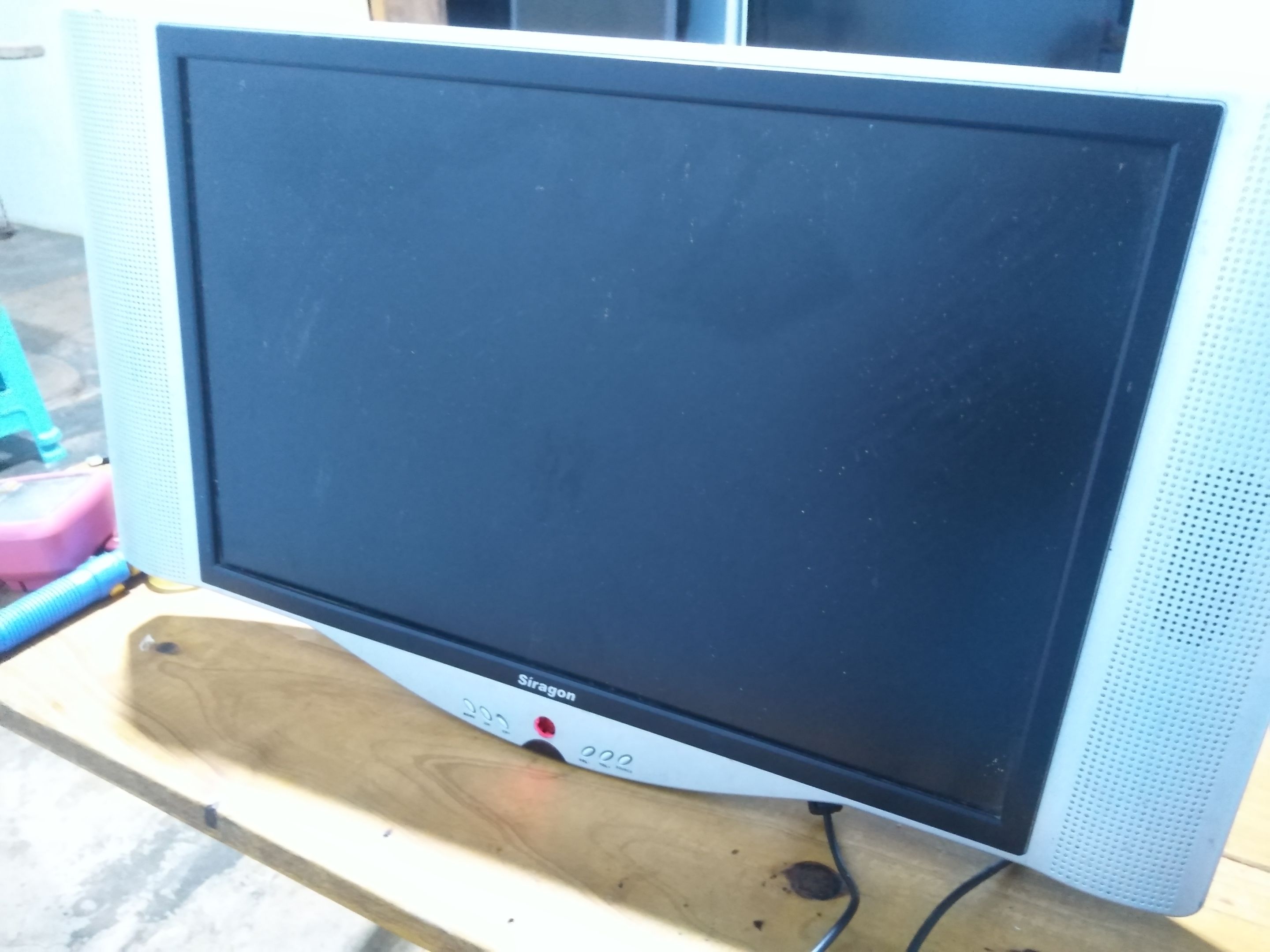
Además de parlantes cuenta con entrada RCA, lo que quiere decir que reproduce imagen y sonido si se le conecta una consola de videojuegos, un DVD, bluray u otro dispositivo reproductor audiovisual.
La clienta me indicó que el monitor había sido llevado a otro taller pero no dieron con la falla y seguía sin encender, así que lo primero que debía hacer era la inspección visual, corroborar que el cable de alimentación de corriente esté en buen estado y el pulsador de Power.
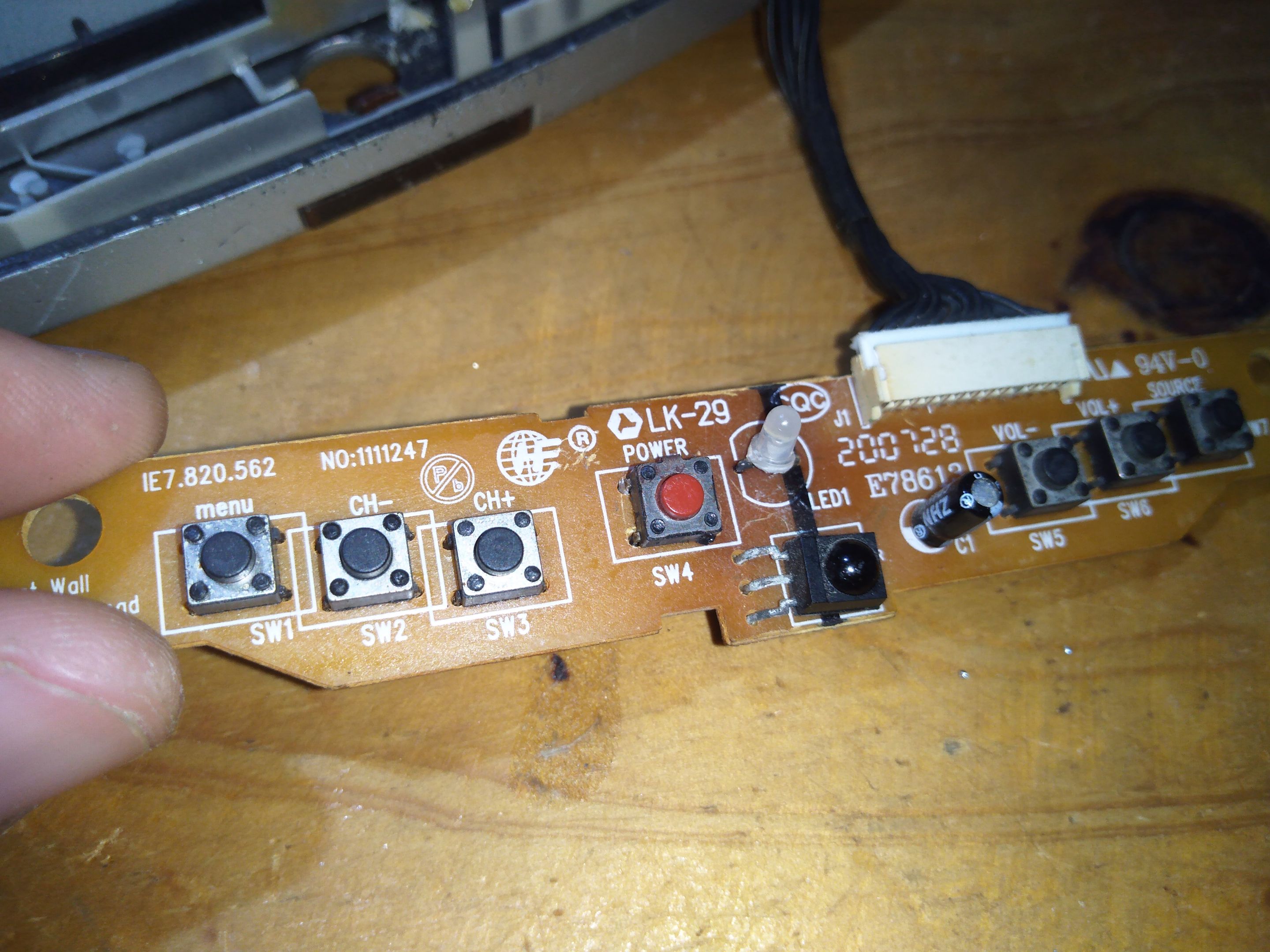
Al realizar la inspección visual pude notar varios elementos de soldados y la placa base bastante deteriorada, pistas rotas etc.
El cable de alimentación estaba bueno, así que pasé a probar el pulsador de Power y este estaba dañado.
In addition to speakers, it has an RCA input, which means that it reproduces image and sound if a video game console, DVD, bluray or other audiovisual player device is connected.
The client told me that the monitor had been taken to another workshop but they did not find the fault and it still did not turn on, so the first thing I had to do was the visual inspection, check that the power cord is in good condition and the Power button.
When performing the visual inspection I could notice several welded elements and the base plate quite deteriorated, broken tracks, etc.
The power cord was good, so I went to test the Power button and it was damaged.
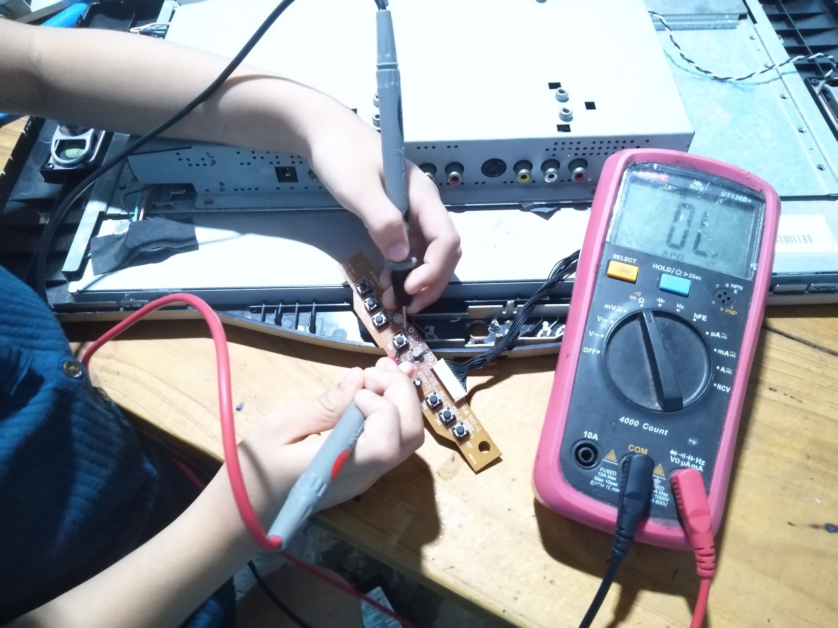
En ocasiones mi niña menor me ayuda, esto también le sirve a ella para ir aprendiendo.
Ella se encargaba de mantener las puntas en los pines del pulsador y yo presionaba el botón para ver si emitía sonido de continuidad.
Al pulsar noté que no se emitía sonido, por lo tanto el pulsador estaba malo.
Sometimes my youngest girl helps me, this also helps her to learn.
She was in charge of keeping the tips on the pins of the pushbutton and I pressed the button to see if it emitted continuity sound.
When I pressed the button I noticed that no sound was emitted, therefore the push button was bad.
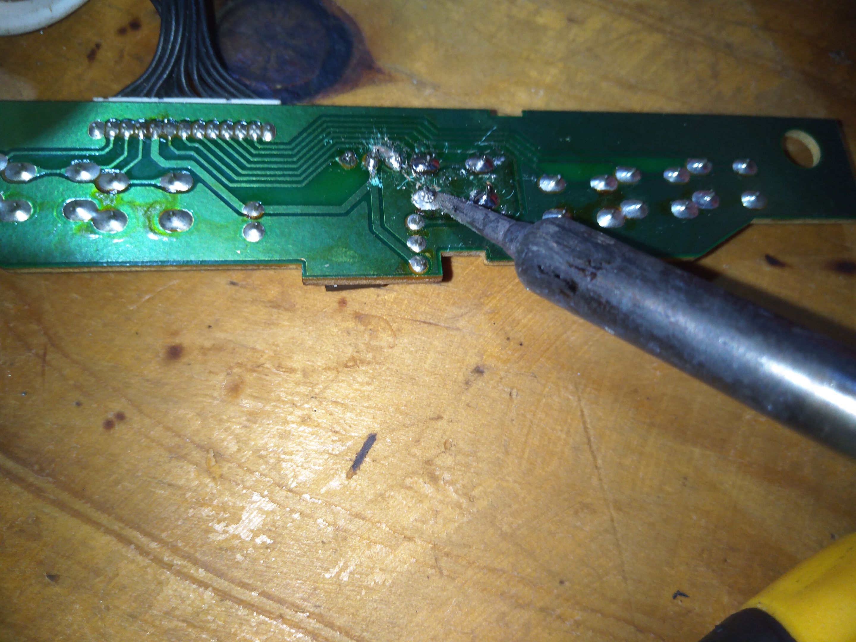
Busqué uno de reciclaje y reemplace el dañado.
Hay que desoldar y volver a soldar el nuevo componente. Ya tenía una parte solucionada, ahora pasaría a la tarjeta que veía más deteriorada y manipulada.
I looked for a recycle one and replaced the damaged one.
The new component had to be unsoldered and re-soldered. I already had one part solved, now I would move on to the board that I saw more deteriorated and manipulated.
Encontré un capacitor cerámico desolado y en la base de la placa se veía un punto de calor, supongo que había quedado mal soldado y por esa razón produjo el punto de calor.
Esta tarjeta es la encargada de generar la iluminación de la pantalla con los Inverter, en este área se genera un fuerte voltaje.
I found a desolated ceramic capacitor and at the base of the board there was a hot spot, I guess it had been poorly soldered and for that reason produced the hot spot.
This board is in charge of generating the display illumination with the Inverters, in this area a strong voltage is generated.
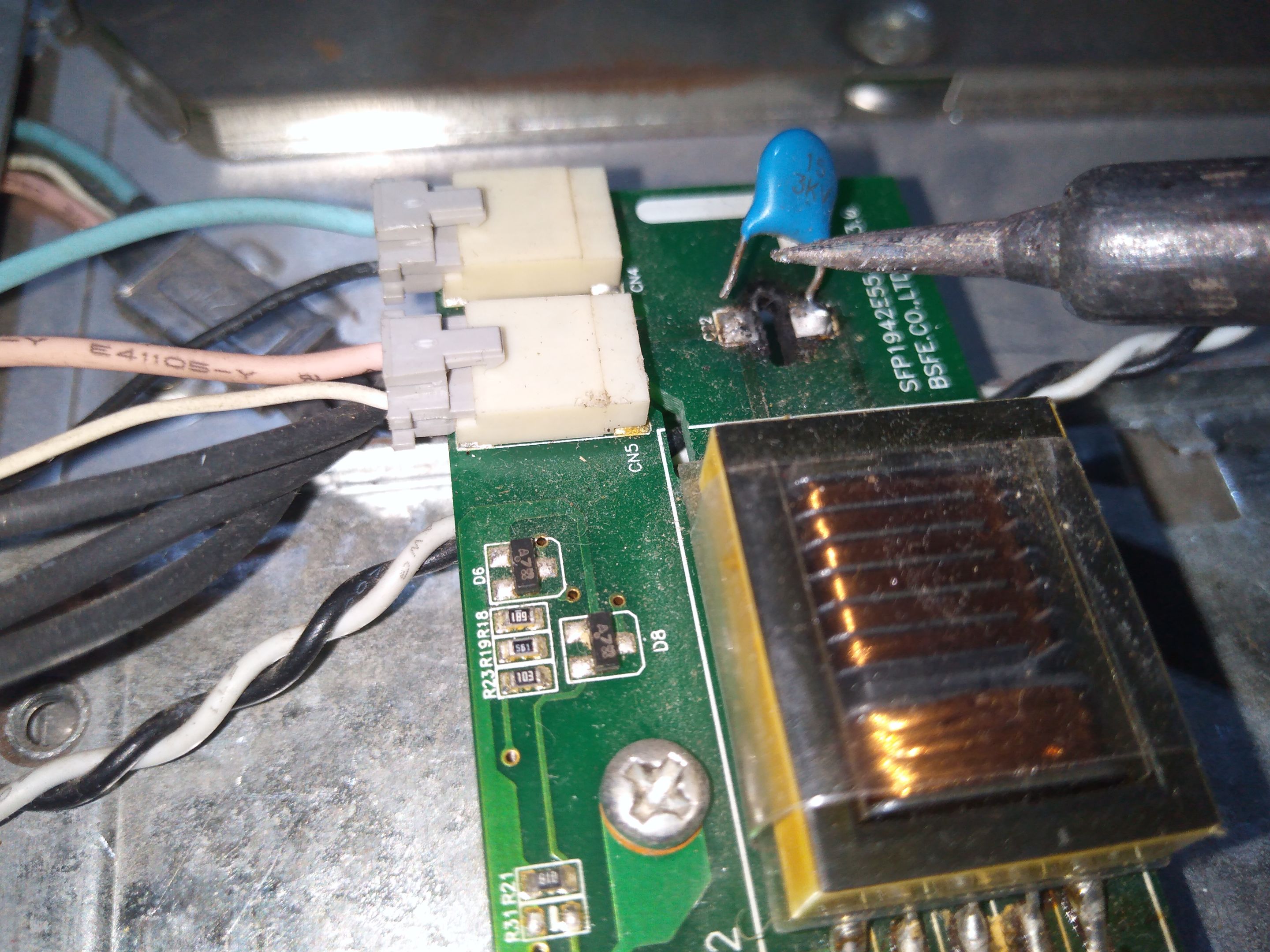
Removi la soldadura dañada, retiré la pista que estaba despegada, volví a raspar la cubierta de la pista en el área buena y resolde.
De esta forma me aseguro que el componente quede bien firme, bien soldado.
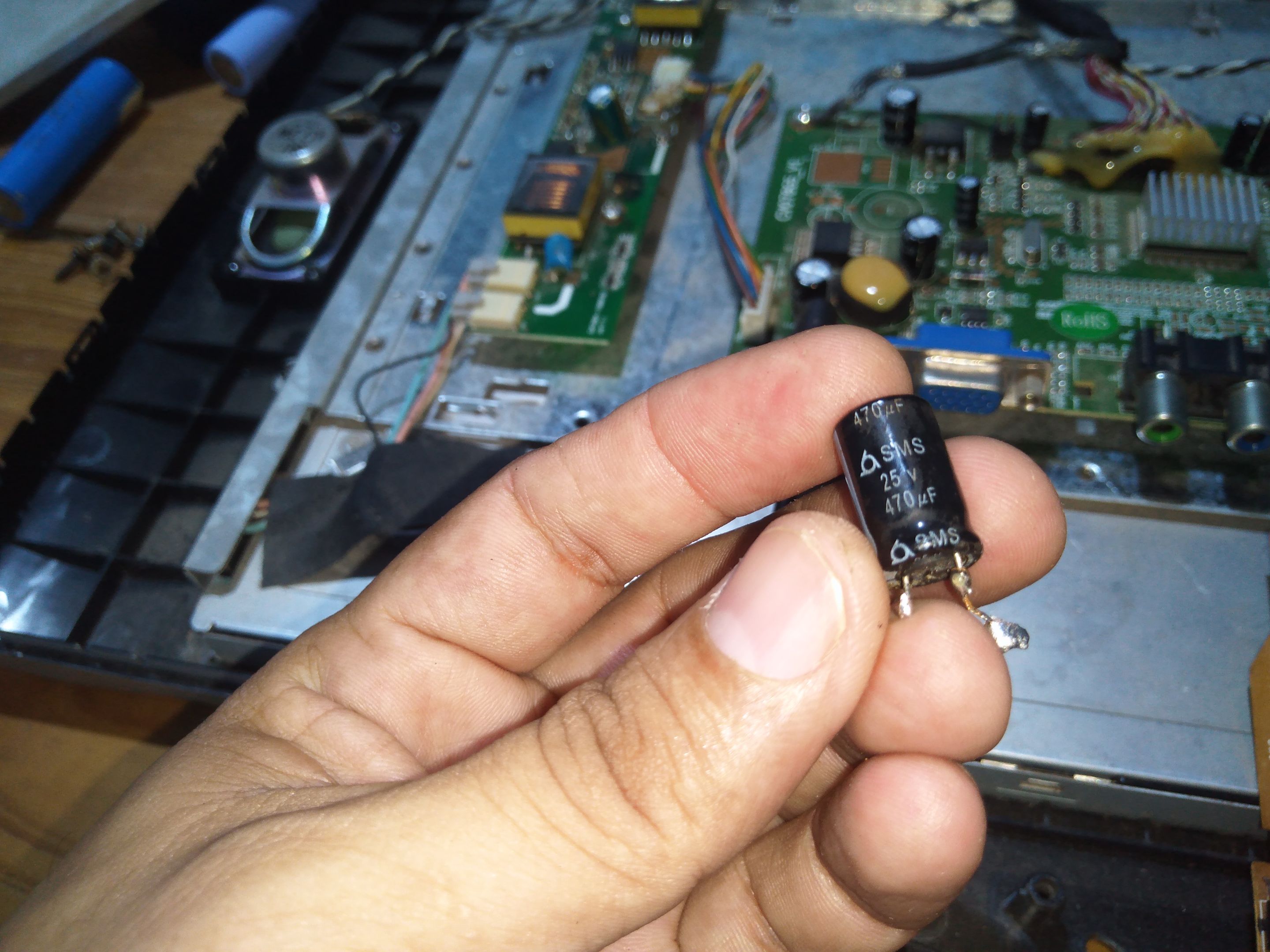
Ahora pasé al área donde estaba un capacitor electrolítico de 470 UF, lo veía un poco deteriorado, pero no estaba inflado, sin embargo lo retire para probarlo con el capacimetro.
I removed the damaged solder, removed the track that was peeling off, re-scraped the track cover in the good area and re-soldered.
This way I make sure that the component is tight, well soldered.
Now I went to the area where was an electrolytic capacitor of 470 UF, I saw it a little deteriorated, but it was not inflated, however I removed it to test it with the capacitance meter.
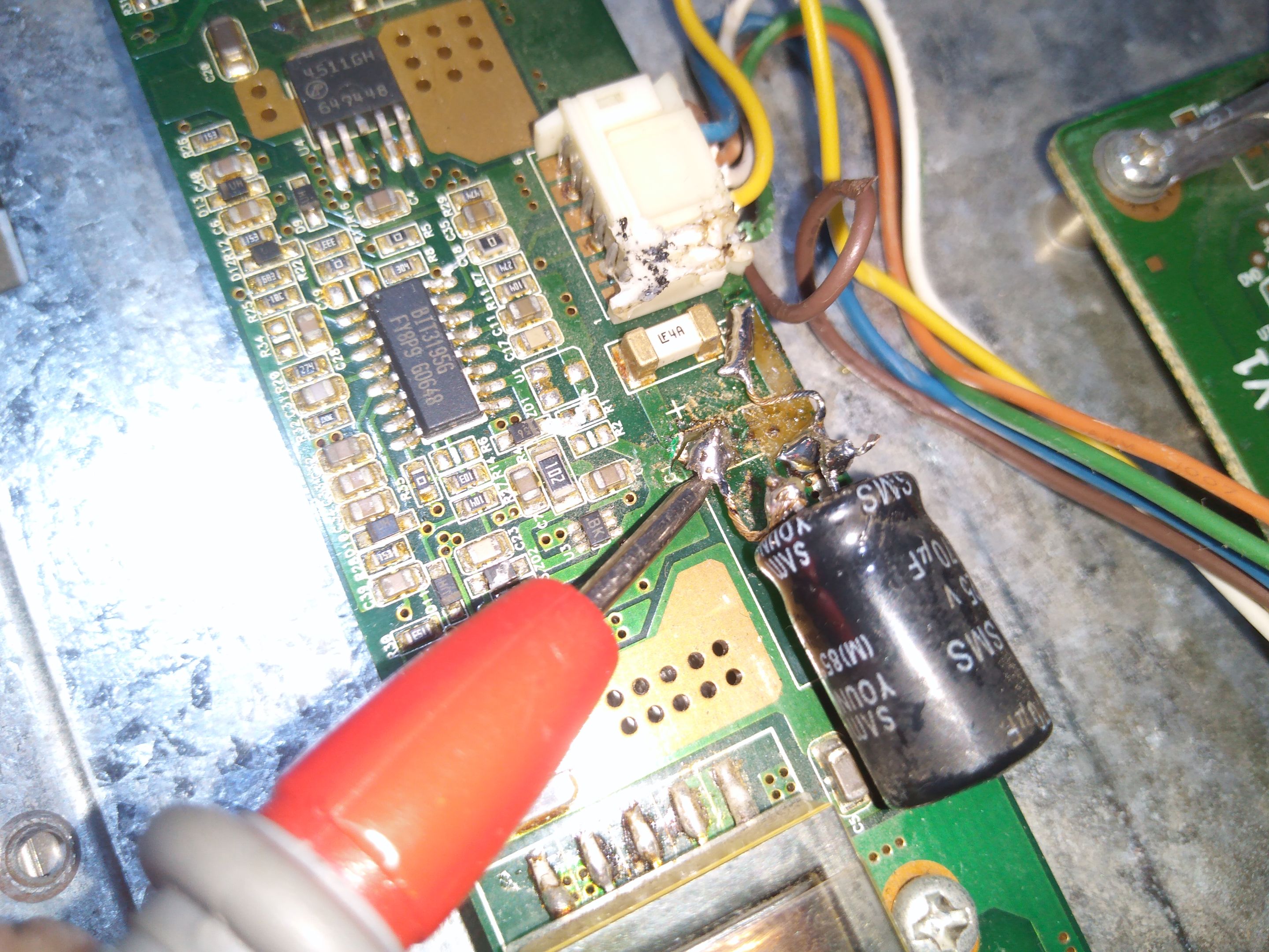
Al probarlo me di cuenta que estaba desgastado, arrojaba una capacitancia de 40 UF. Así que volví a retirar la soldadura de estaño, retiré la pista dañada, raspe y coloqué un capacitor nuevo.
When I tested it I realized that it was worn, it was throwing a capacitance of 40 UF. So I removed the tin solder, removed the damaged track, scraped and put a new capacitor.
Ya el área que estaba afectada había sido restaurada, por lo tanto solo faltaba hacer la prueba de encendido.
Sí no había más daño debería de prender y mostrar imágen.
The area that was affected had already been restored, so all that was left to do was to do the power-on test.
If there was no further damage it should turn on and display an image.
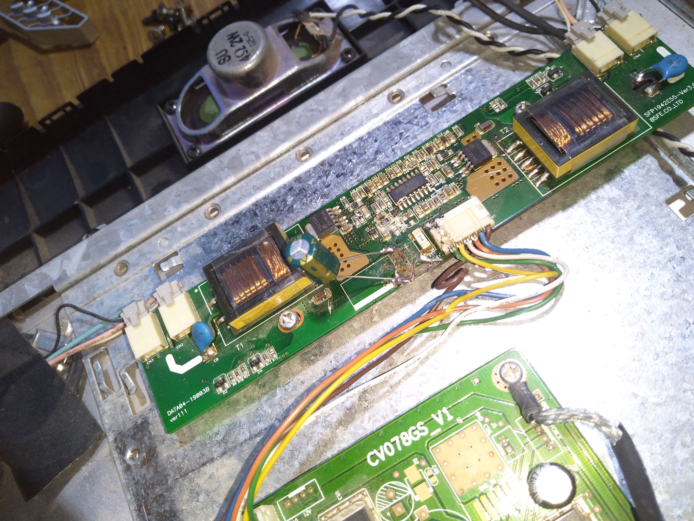
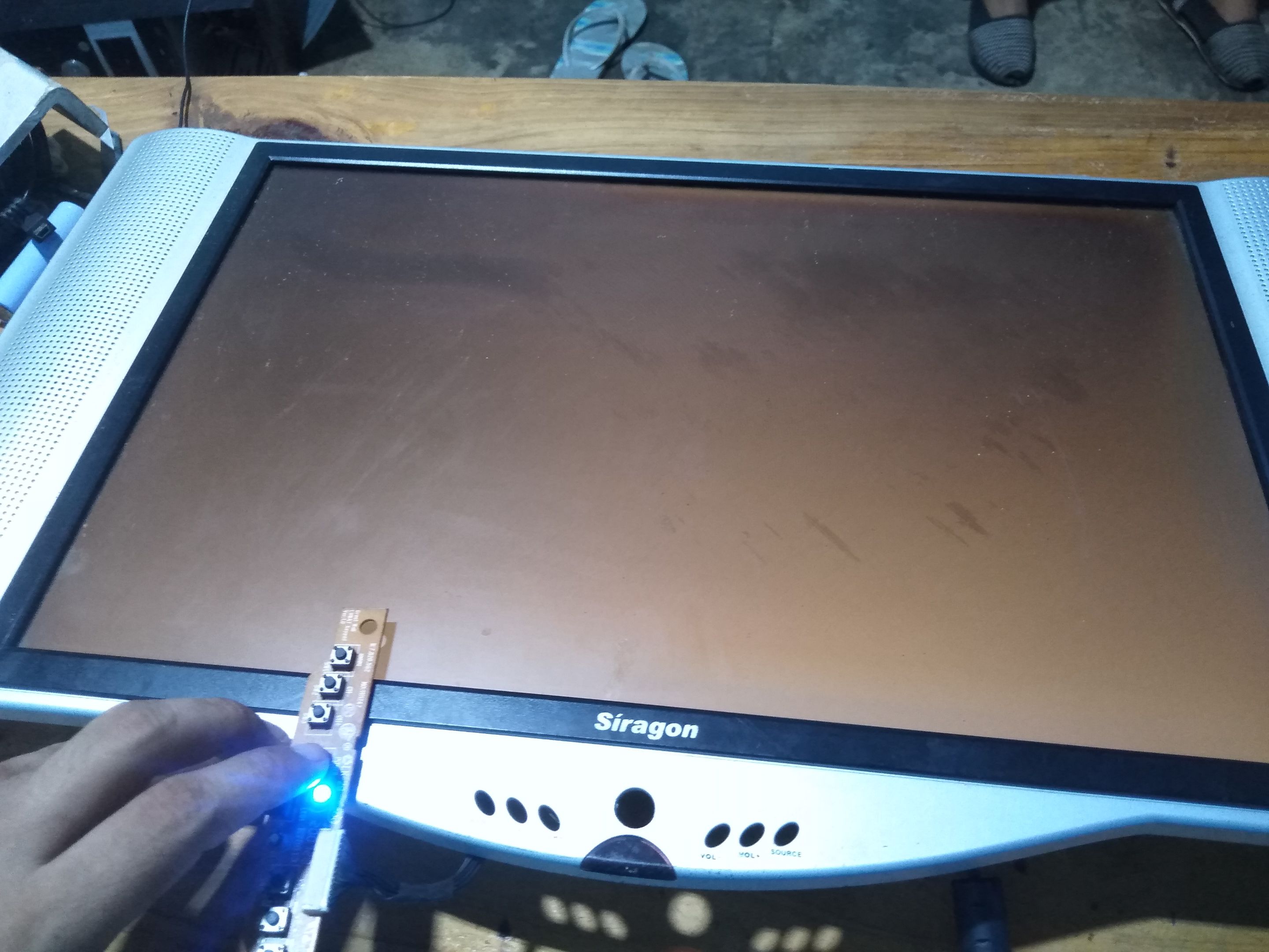
Enchufe el monitor y presioné el botón de Power, el monitor encendió pero no mostró imágen, solo se ilumina la luz blanca que ilumina la pantalla LCD.
Esto quiere decir que ahora debo revisar la tarjeta lógica donde está integrado el circuito de video.
Debido al deterioro no me podía esperar nada fácil, hubiese sido maravilloso que todo saliera bien a la primera, pero así es la electrónica.
I plugged in the monitor and pressed the Power button, the monitor turned on but did not show any image, only the white light that illuminates the LCD is illuminated.
This means that now I have to check the logic board where the video circuit is integrated.
Due to the deterioration I could not expect anything easy, it would have been wonderful if everything went right the first time, but that's electronics.
En un un próximo tutorial les mostraré la segunda parte de este tutorial, donde se revisará la tarjeta lógica.
Espero que el monitor tenga reparación y que no haya un daño significativo, de lo contrario pasará al área de donantes de componentes.
Espero les haya gustado esta primera parte del tutorial.
Nos vemos en una próxima oportunidad.
In a next tutorial I will show you the second part of this tutorial, where the logic board will be checked.
I hope that the monitor is repairable and that there is no significant damage, otherwise it will go to the component donor area.
I hope you liked this first part of the tutorial.
See you next time.
Todas las fotografías fueron tomadas con mí Smartphone Huawei Dub-Al00.
Traducido con Deepl
)