Saludos Hivers aficionados a la tecnología y la electrónica.
Es un gusto para mí volver a compartir con toda la comunidad un nuevo tutorial.
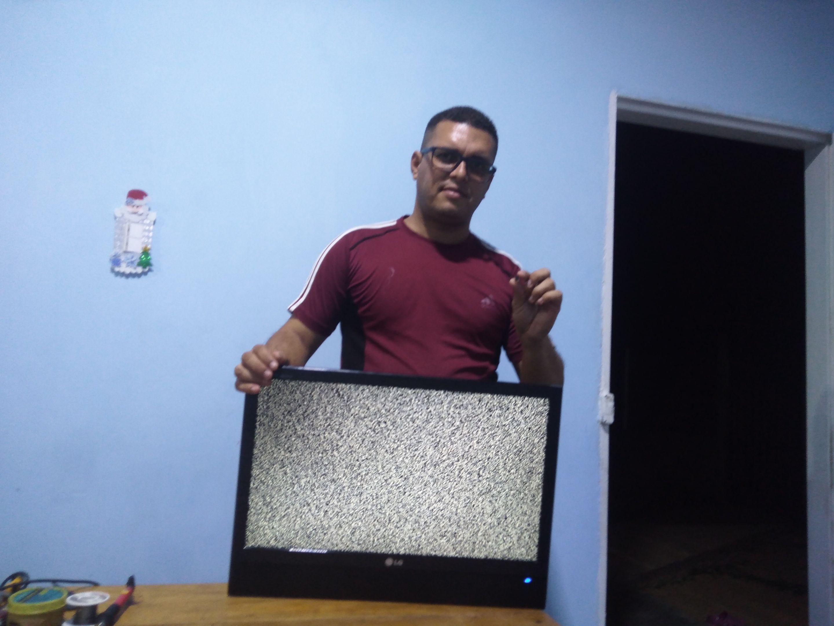
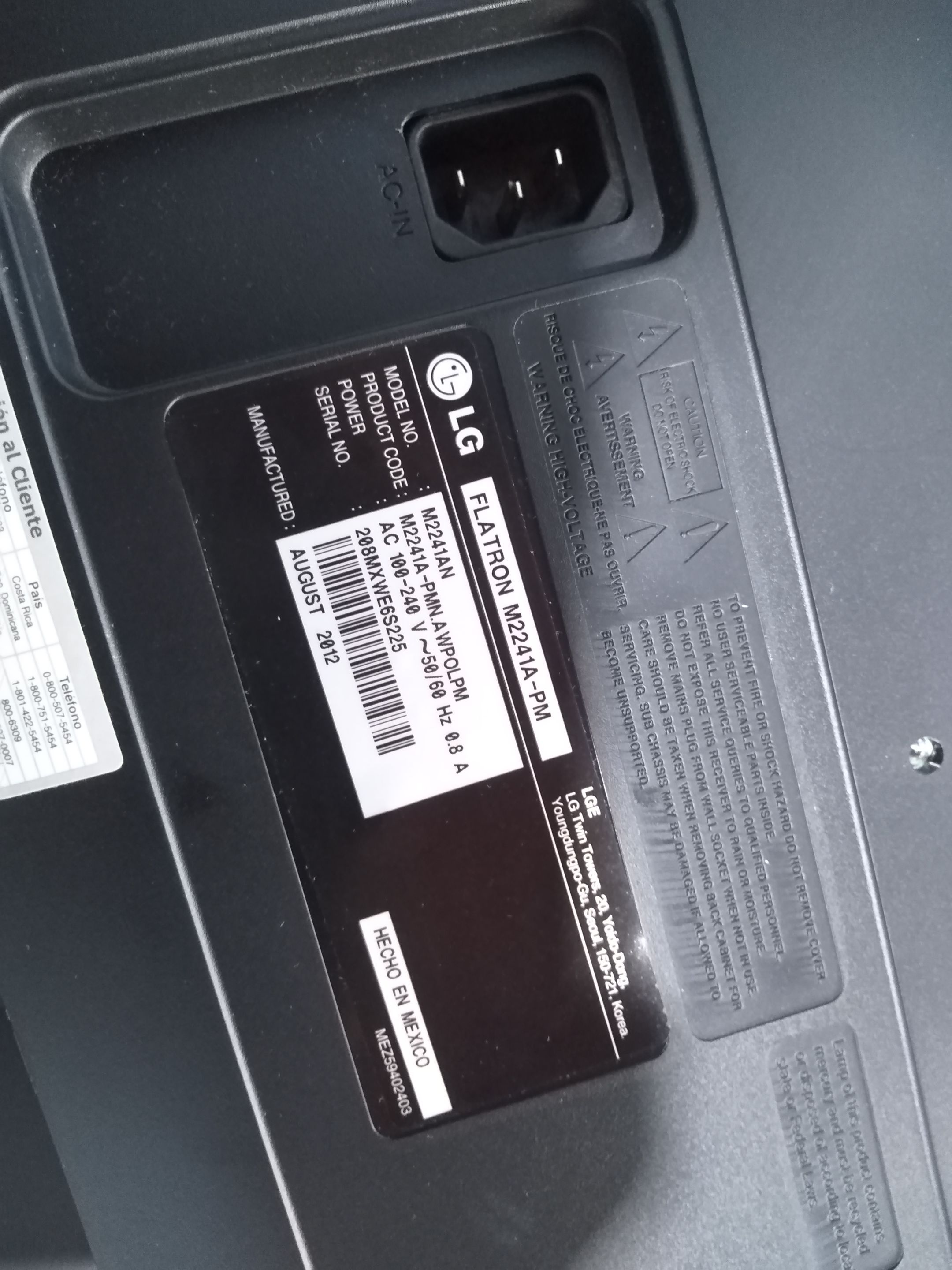
En esta oportunidad se trata de la reparación de un televisor LCD marca LG modelo Flatron M2241AN.
Greetings Hivers fans of technology and electronics.
It is a pleasure for me to share with the whole community a new tutorial.
This time it is about the repair of a LCD TV brand LG Flatron model M2241AN.
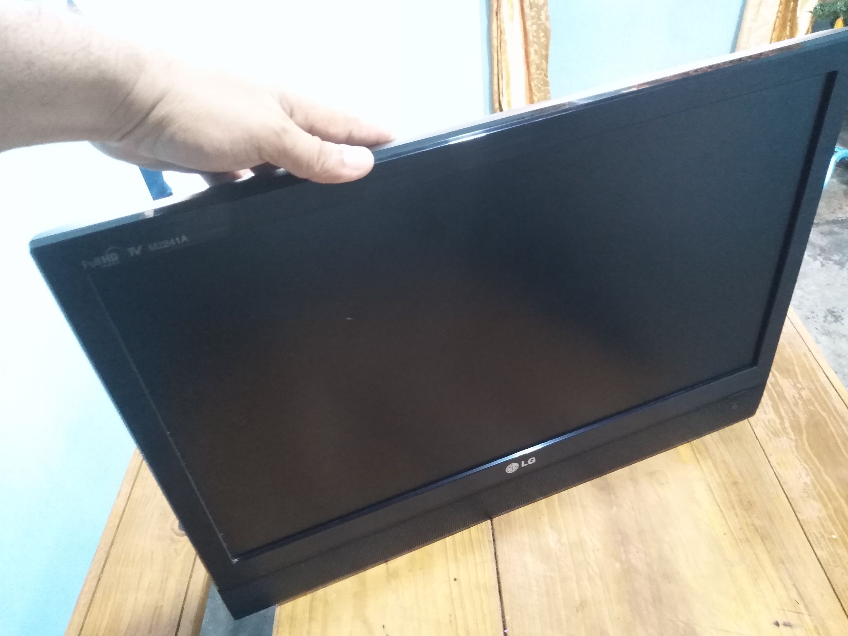
La falla de este televisor era que no encendía. No había luz indicadora de stand by, esta es una de las señales de que hay una falla en la fuente de poder, pero como siempre indico en mis tutoriales, si el artefacto no prende, debemos revisar el cable de alimentación.
The failure of this TV was that it did not turn on. There was no stand by indicator light, this is one of the signs that there is a failure in the power supply, but as I always indicate in my tutorials, if the device does not turn on, we must check the power cord.
Al revisar el cable con el tester en la escala de continuidad pude cerciorarme de que el cable estaba en buen estado.
Ahora si podemos proceder a destapar el televisor, estos televisores tienen la misma estructura de un monitor, tanto en la parte externa como interna,la diferencia la tienen en la tarjeta lógica.
When checking the cable with the tester on the continuity scale I could make sure that the cable was in good condition.
Now if we can proceed to uncover the TV, these televisions have the same structure of a monitor, both externally and internally, the difference is in the logic card.
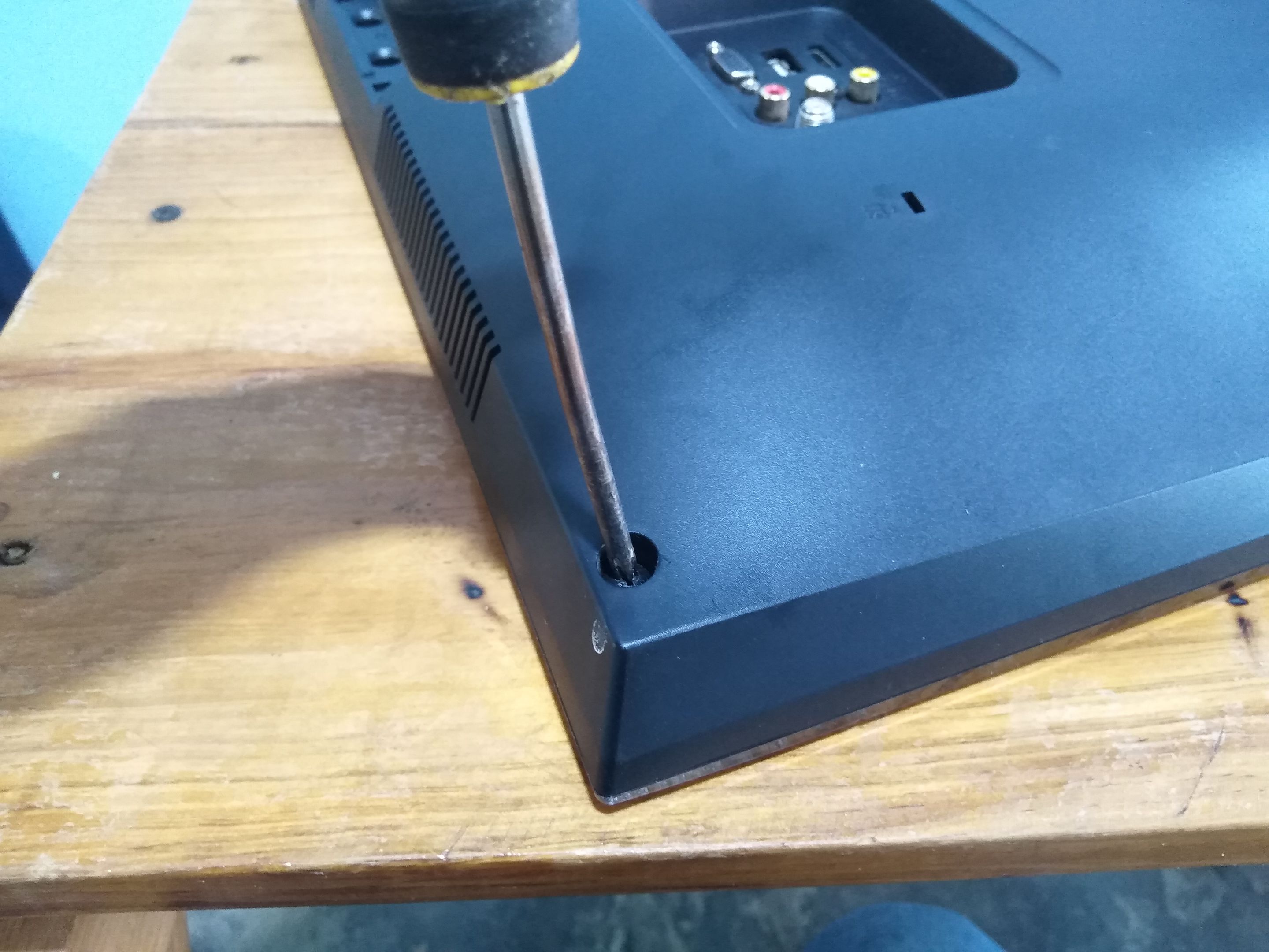
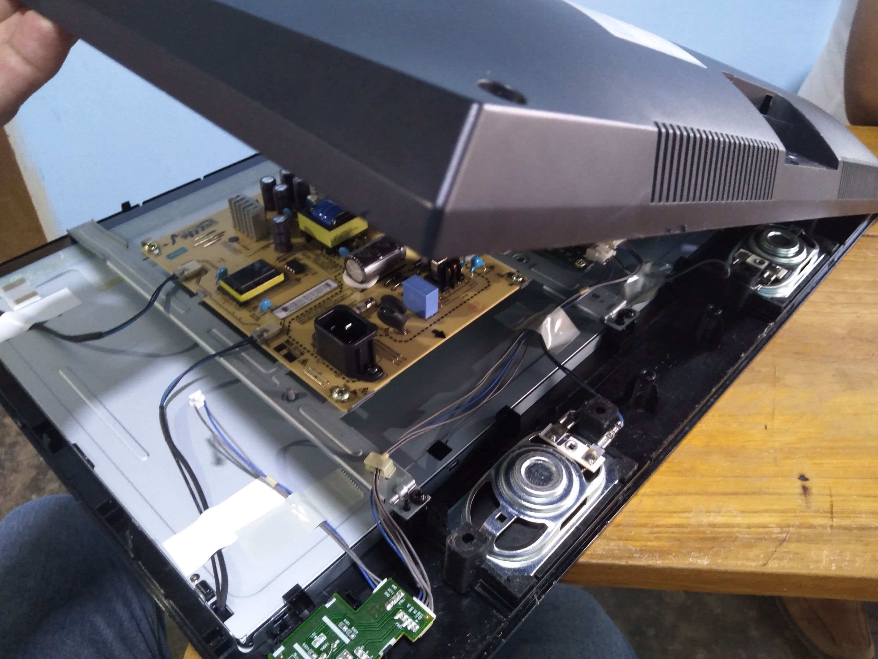
Para destapar el televisor sacamos los tornillos de la carcasa y luego con un destornillador de pala o una uña de plástico hacemos palanca por la orilla de la tapa.
To uncover the TV, remove the screws from the housing and then use a screwdriver or a plastic nail to pry the edge of the cover.
De esta forma destapamos el televisor para luego visualizar las tarjetas electrónicas.
Estos aparatos tienen la misma ubicación de las tarjetas,incluso los colores de las placas también son iguales.
In this way we uncover the TV set to then visualize the electronic cards.
These devices have the same location of the cards, even the colors of the boards are also the same.
En el centro encontraremos la tarjeta de la fuente de poder, esta es de color crema y las demás tarjetas lógicas están distribuidas a los lados y en la parte superior, estas son de color verde.
Identificamos la tarjeta de la fuente de poder porque en ella se encuentra el conector del cable de corriente.
In this way we uncover the TV set to then visualize the electronic cards.
These devices have the same location of the cards, even the colors of the boards are also the same.
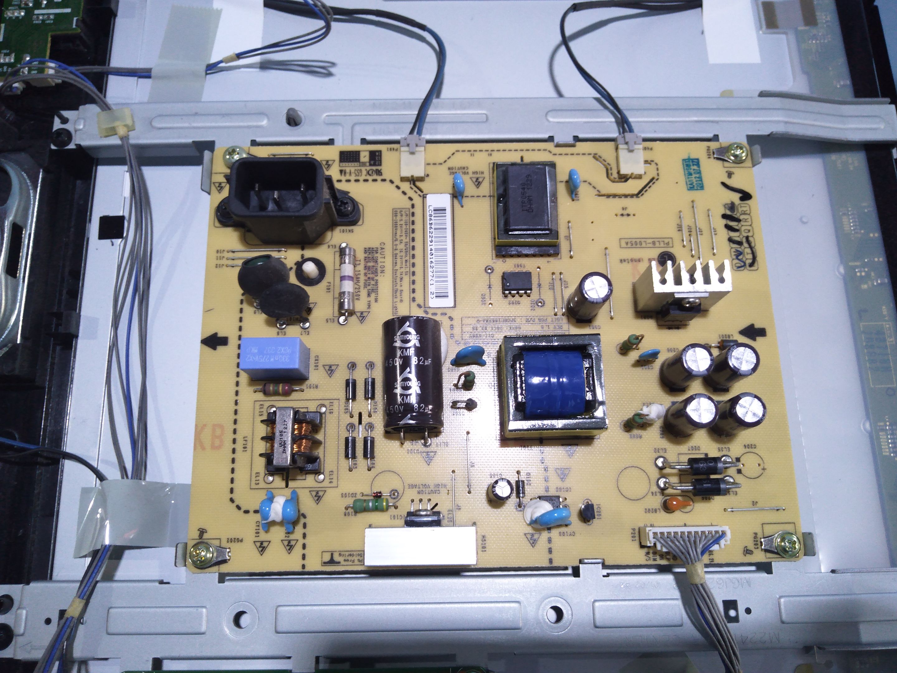
En esta tarjeta también encontremos un transformador grande m, un capacitor grande y otros componentes electrónicos.
Ahora, como el televisor no enciende tendremos que revisar con el tester en la escala de continuidad todos componentes importantes, como lo son: fusible, puente rectificador, diodos, transistores, capacitor principal y capacitores de salida.
Este televisor tenía en buen estado los capacitores, fusibles, diodos, pero encontré un corto en un diodo doble.
On this board we also find a large transformer, a large capacitor and other electronic components.
Now, as the TV does not turn on we will have to check with the tester on the continuity scale all important components, such as: fuse, bridge rectifier, diodes, transistors, main capacitor and output capacitors.
This TV had in good condition the capacitors, fuses, diodes, but I found a short in a double diode.
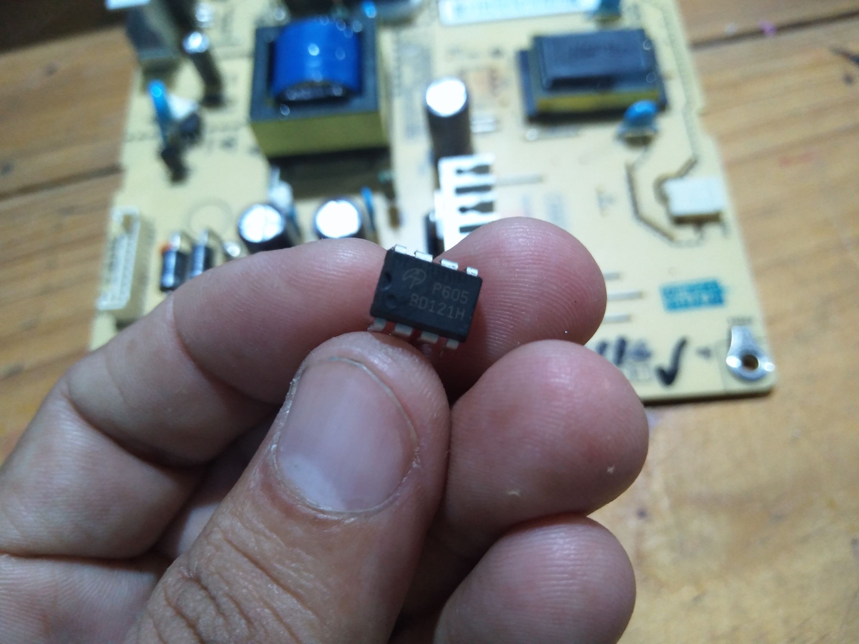
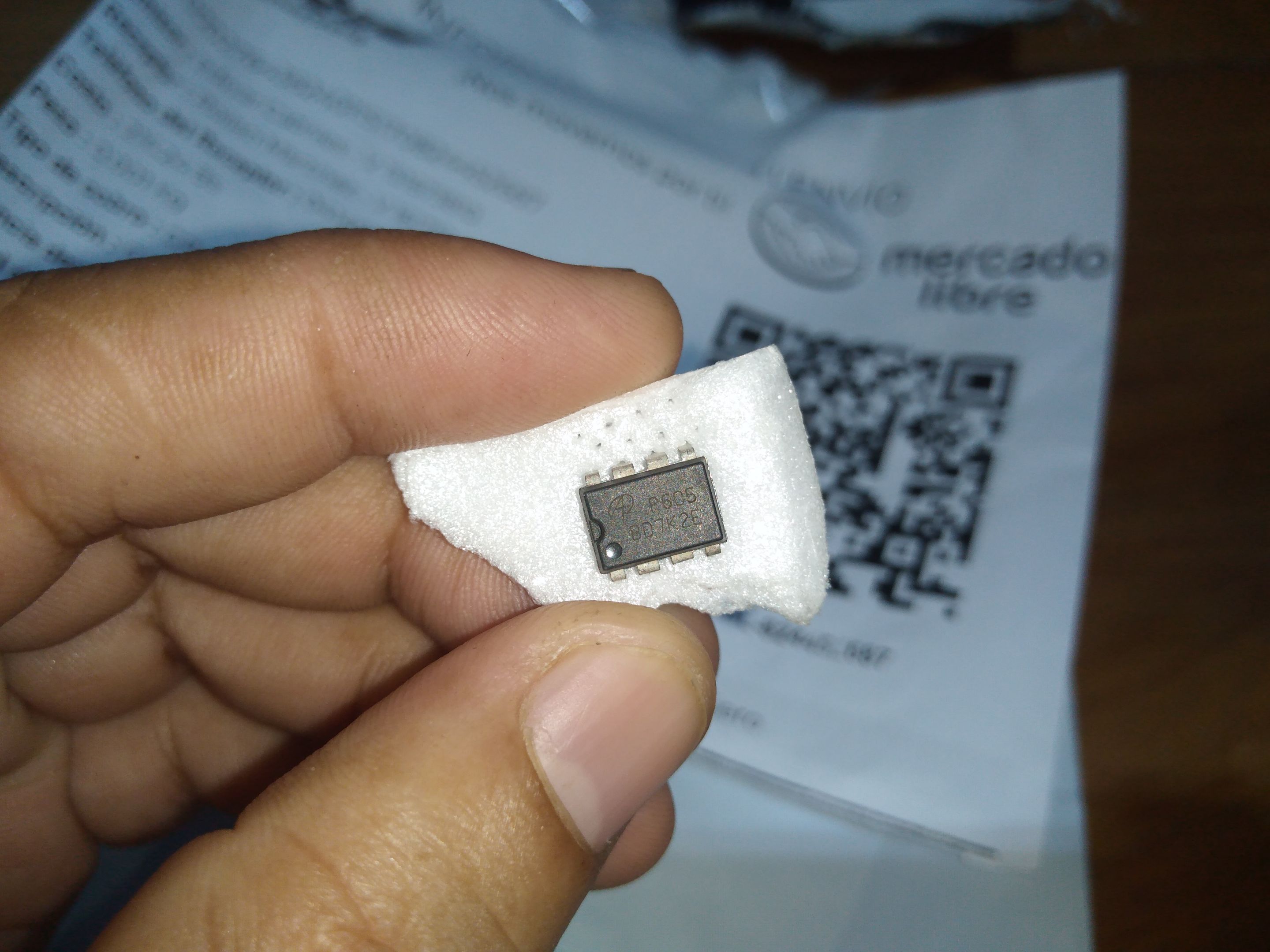
Este diodo doble estaba asociado a un MOSFET dual, entonces decidí desoldar el MOSFET dual que me daba corto en el emisor y colector, tanto en el lado NPN como en el PNP.
Pero para saber sí un circuito integrado de estos está malo, debemos buscar la hoja de datos según su nomenclatura.
Este es un MOSFET P605
This dual diode was associated to a dual MOSFET, so I decided to desolder the dual MOSFET that gave me short in the emitter and collector, both in the NPN and PNP side.
But to know if one of these integrated circuits is bad, we must look for the data sheet according to its nomenclature.
This is a P6 MOSFET
05
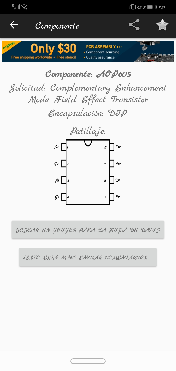
Con la identificación de las patas podemos saber dónde testear para ver si hay un corto o no.
Al final del post dejaré un vídeo para que puedan ver la diferencia en la medición entre el MOSFET dañado y el bueno.
Ya sabiendo cuál es el componente dañado, podemos pedirlo a la tienda de electrónica.
With the identification of the legs we can know where to test to see if there is a short or not.
At the end of the post I will leave a video so you can see the difference in the measurement between the damaged MOSFET and the good one.
Already knowing which is the damaged component, we can ask for it to the electronics store.
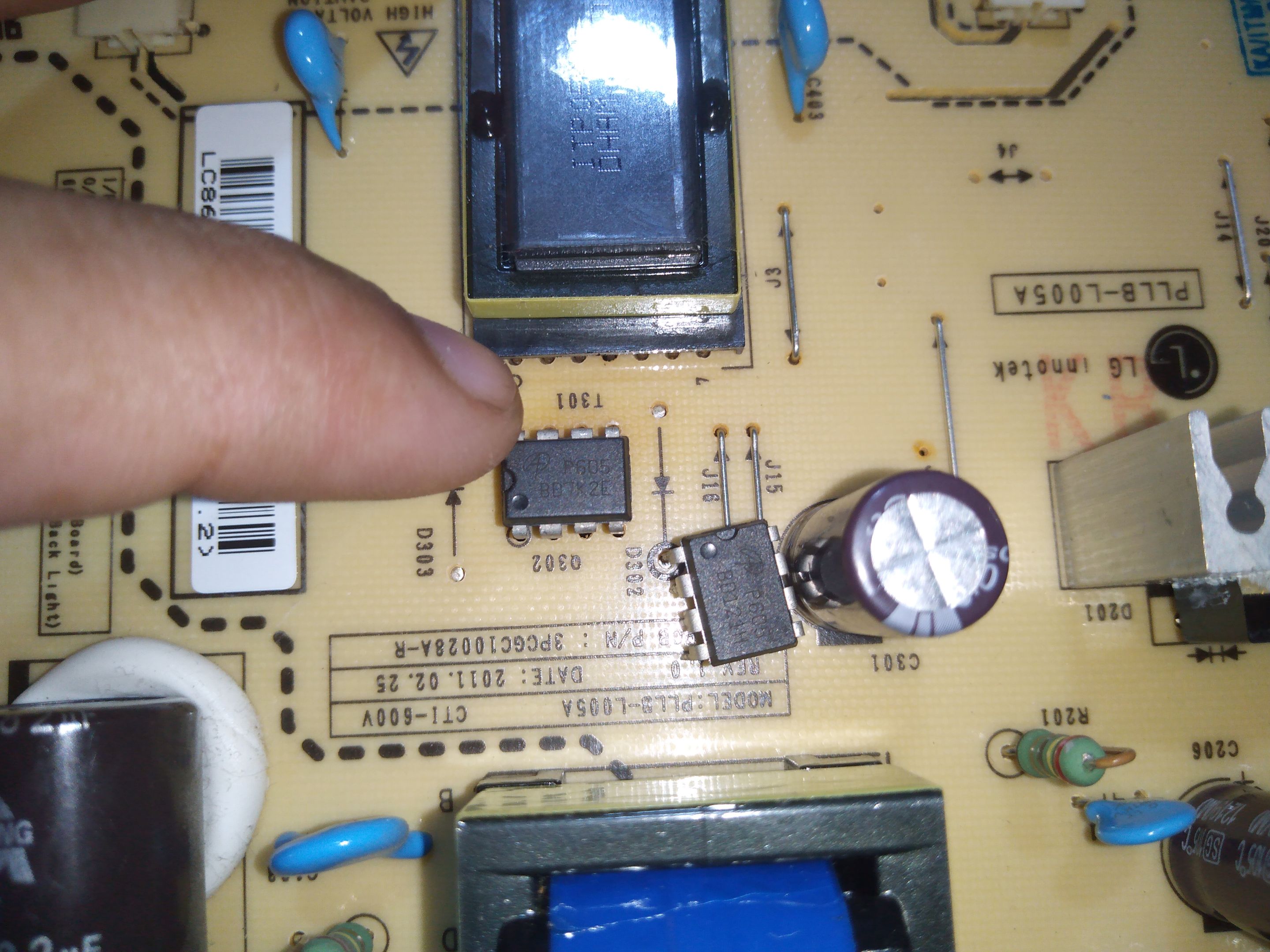
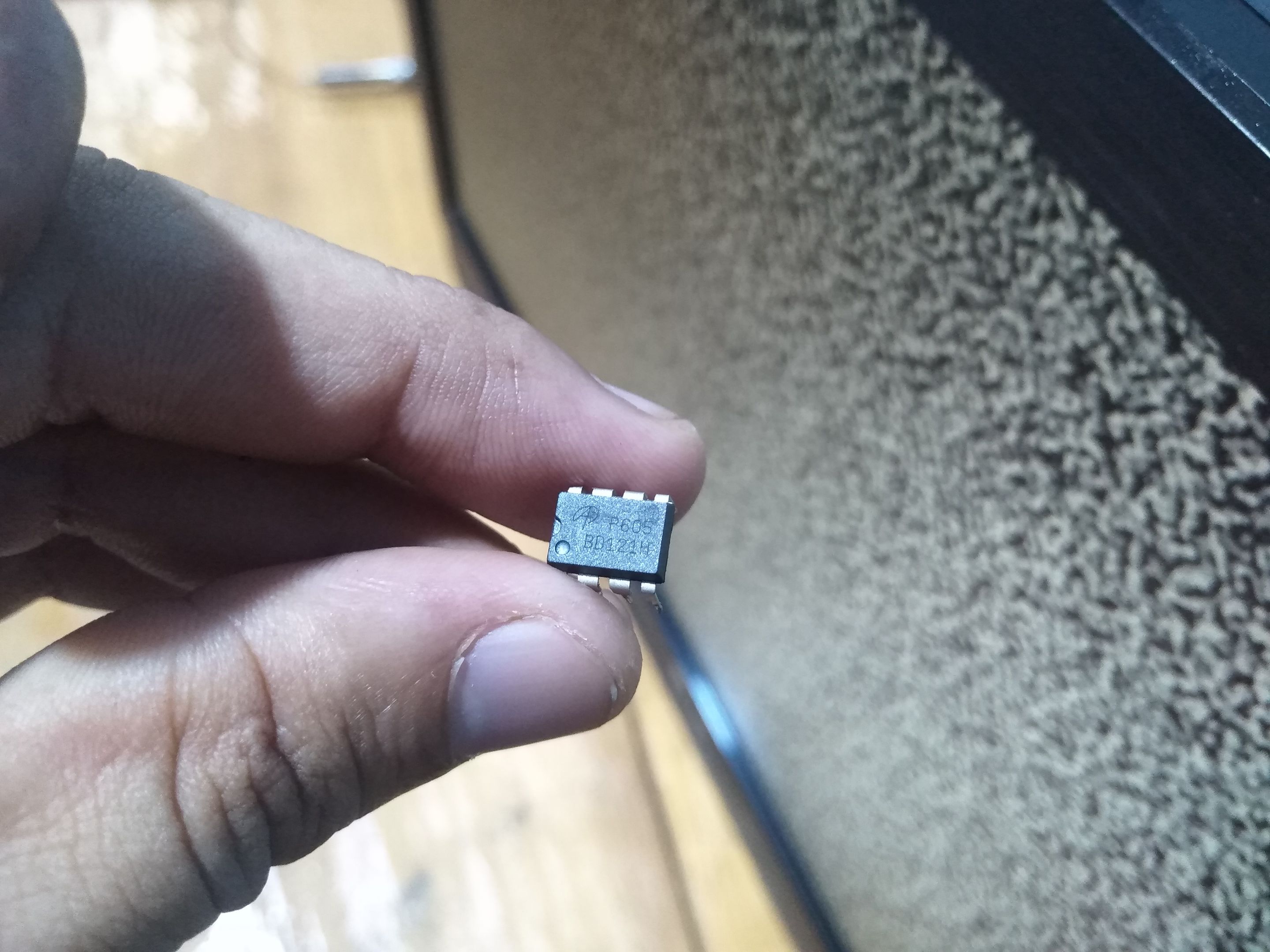
Aquí tenemos el MOSFET dual nuevo, ahora procedemos a colocarlo en su lugar.
Los circuitos integrados tienen una marca para indicar cuál es la posición correcta y en la placa también se encuentra esta marca.
Here we have the new dual MOSFET, now we proceed to put it in place.
The integrated circuits have a marking to indicate the correct position and the board also has this marking.
a.
Así que es muy poco probable que un técnico se pueda confundir al momento de colocar el componente, a menos que esté descuidado y que no revise bien al terminar el trabajo.
Una vez soldado el MOSFET volvemos a medir en la zona donde antes había corto y si todo está bien procedemos a enchufar y encender el TV.
So it is very unlikely that a technician can be confused at the time of placing the component, unless he is careless and does not check well when finishing the job.
Once the MOSFET is soldered we measure again in the area where before there was a short and if everything is OK we proceed to plug and turn on the TV.
Aquí vemos el televisor encendido, quiere decir que le hemos dado solución a este televisor.
La utilización de una herramienta como el tester es muy importante para poder lograr estos resultados, además de saber cómo hacer las mediciones respectivas.
Cuando no somos muy diestros en la detección de componentes dañados por la falta de conocimiento en cuanto a la medición, podemos omitir estos integrados y no logramos solventar la falla.
Aquí les muestro el video:
Here we see the TV on, it means that we have given solution to this TV.
The use of a tool such as the tester is very important to achieve these results, in addition to knowing how to make the respective measurements.
When we are not very skilled in detecting damaged components due to lack of knowledge in terms of measurement, we can omit these integrated and fail to solve the fault.
Here I show you the video:
Espero que esté tutorial les sirva en el futuro como guía de reparación y más aún si tienen este modelo de televisor en casa.
Hasta un próximo tutorial.
I hope this tutorial will be useful in the future as a repair guide and even more if you have this TV model at home.
Until a future tutorial
al.
Traducido con Deepl
Todas las fotografías fueron tomadas con mí Smartphone Huawei Dub-Al00.