Measure the voltage at a point is very important when diagnosing faults, verify the operation of an electronic system and establish criteria for protections.
The most practical way to measure a voltage is with a voltmeter, we place the tips in the places where we want to make the measurement and the value is obtained, however, if we want a system can protect itself and other equipment from unwanted voltage levels this must be able to measure the voltage on the line at all times without human intervention to take protective actions when appropriate.
In this article we will learn how to measure AC voltage values using a PIC18F2550 microcontroller and the True rms measurement method, we will implement and explain a basic circuit to sample the voltage and the program that allows measurements to be made from that sample.
Medir el voltaje en un punto es muy importante a la hora de diagnosticar fallas, verificar el funcionamiento de un sistema electrónico y establecer criterios de protecciones.
La forma más práctica para medir un voltaje es con un voltímetro, colocamos las puntas en los lugares donde queremos hacer la medición y se obtiene el valor, sin embargo, si queremos que un sistema pueda protegerse a sí mismo y a otros equipos de niveles de voltaje no deseados este debe ser capaz de poder medir el voltaje en la línea en todo momento sin intervención humana para tomar las acciones de protección cuando corresponda.
En este artículo aprenderemos a medir valores de voltaje AC usando un microcontrolador PIC18F2550 y el método de medición True rms, se implementará y explicará un circuito básico para tomar una muestra del voltaje y el programa que permite hacer las mediciones a partir de dicha muestra.
Theoretically we represent the AC voltage of the public network as a pure sine wave, this implies that if we want to measure the voltage at an instant of time the measured value may vary depending on the point where the level is at that time, it may even be 0 because the wave crosses the 0 value 2 times per cycle and that does not imply that there are problems with the voltage.
For convenience is established for an AC voltage an effective value that is equivalent to the voltage that would have a DC source, one way to do this is with the RMS measurement (Root Mean Squared) or mean square value, to obtain this value is necessary to know the maximum value of the wave also known as Peak Voltage or Vp and is divided by root of 2 or 1.414.
However the rms measurement is only useful if the signal is pure sinusoidal, in reality there are many disturbances that can introduce noise to the shape of the signal, a measurement that ignores the waveform and can capture the rms value without taking into account the noise is the True RMS measurement.
To find the True RMS value the following formula can be used:
Teóricamente representamos el voltaje AC de la red pública como una onda sinusoidal pura, esto implica que si queremos medir el voltaje en un instante de tiempo el valor medido puede variar dependiendo del punto en el que se encuentre el nivel en ese momento, incluso puede ser 0 porque la onda cruza por el valor 0 2 veces por ciclo y eso no implica que haya problemas con el voltaje.
Por conveniencia se establece para un voltaje AC un valor eficaz que es equivalente al voltaje que tendría una fuente DC, una forma de hacerlo es con la medición RMS (Root Mean Squared) o valor cuadrático medio, para obtener este valor es necesario conocer el valor máximo de la onda también conocido como Voltaje Pico o Vp y se divide entre raíz de 2 o entre 1.414.
Sin embargo la medición rms solo es útil si la señal es sinusoidal pura, en la realidad existen muchas perturbaciones que pueden introducir ruido a la forma de la señal, una medición que ignora la forma de onda y puede captar el valor eficaz sin tomar en cuenta el ruido es la medición True RMS.
Para hallar el valor True RMS se puede usar la siguiente fórmula:
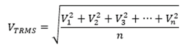
To calculate the true RMS value several measurements are made in the same cycle of the signal, the square root of the average of the squares of the measurements taken is obtained, it can be confusing but the formula exposes it in a clearer way.
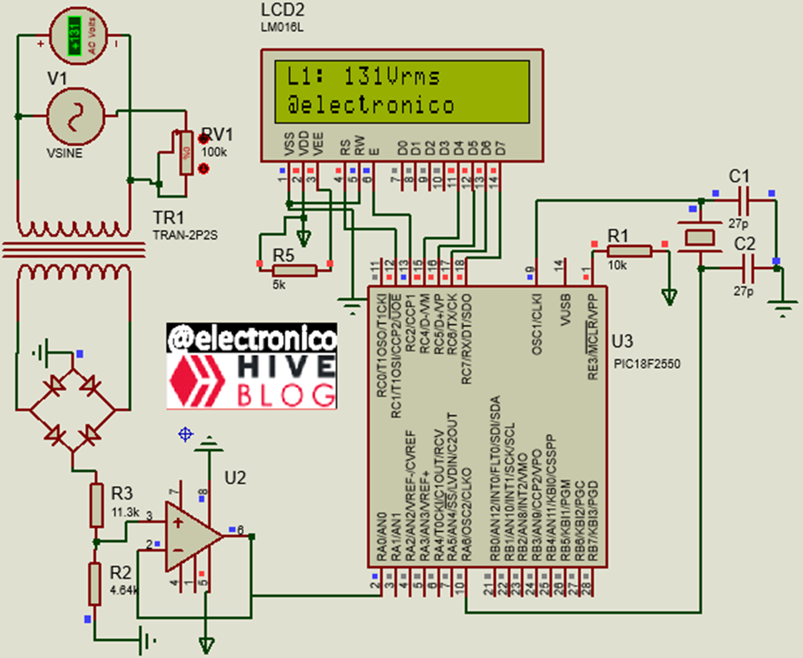
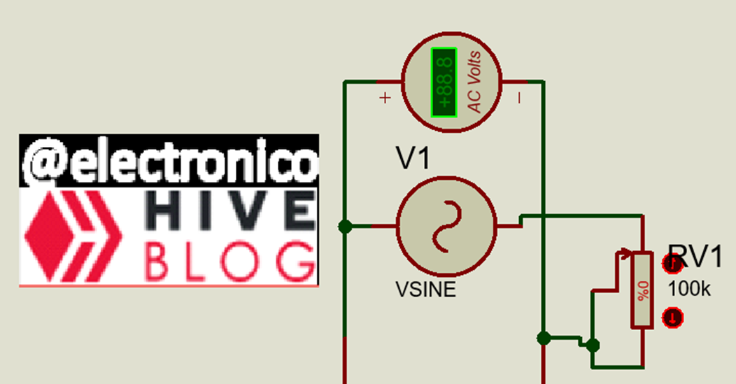
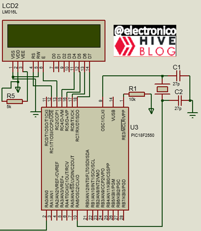
In our circuit we will use an AC voltage source, we will place a potentiometer that will serve to introduce variations in voltage and a multimeter that will serve to compare the measurement that we are going to program with the measurement of this multimeter.
Para calcular el verdadero valor eficaz se hacen varias mediciones en un mismo ciclo de la señal, se obtiene la raíz cuadrada del promedio de los cuadrados de las medidas tomadas, puede ser confuso pero la fórmula lo expone de una forma más clara.
En nuestro circuito vamos a usar una fuente de voltaje AC, colocaremos un potenciómetro que servirá para introducir variaciones en el voltaje y un multímetro que servirá para comparar la medición que vamos a programar con la medición de este multímetro.
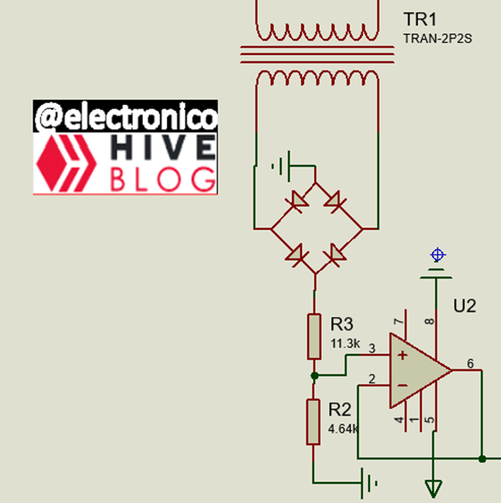
How we will make the measurements with a PIC18F2550 we need to condition the signal to be measured, for this we lower the voltage level with a 10:1 ratio transformer and then using a bridge rectifier we convert the negative peak into positive, in this way we can include it in the measurement.
Once we have the pulsed voltage we apply a voltage divider to add a second stage of voltage reduction and have a control of the minimum and maximum values that will read the ADC of the microcontroller, we take the signal through an operational amplifier in voltage follower mode saturating its output at 5V for ADC protection.
Cómo haremos las mediciones con un PIC18F2550 se necesita acondicionar la señal a medir, para ello se baja el nivel de voltaje con un transformador de relación 10:1 y luego mediante un puente rectificador convertimos en positiva la cresta negativa, de esta forma podemos incluirla en la medición.
Una vez que se tiene el voltaje pulsátil se aplica un divisor de voltaje para añadir una segunda etapa de reducción de voltaje y tener un control de los valores mínimos y máximos que leerá el ADC del microcontrolador, tomamos la señal mediante un amplificador operacional en modo seguidor de tensión saturando su salida a 5V para protección del ADC.
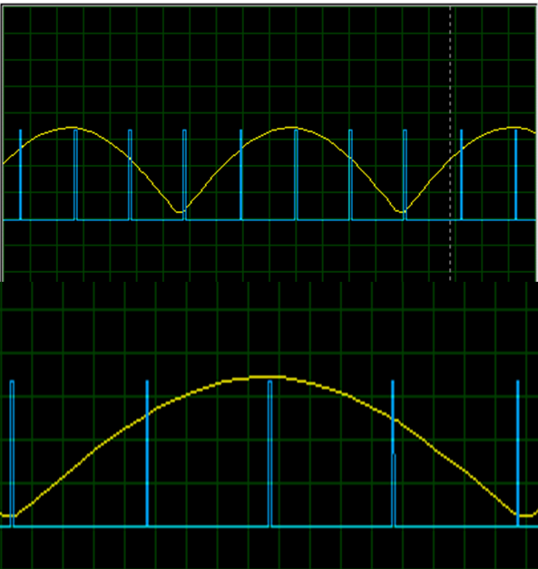
The ADC will take samples in each period of the signal to make the conversion to the True RMS value, we can illustrate the sampling in the following image in which each blue pulse represents the instant in which a sample of the signal marked in yellow is taken:
El ADC se encargará de tomar muestras en cada periodo de la señal para hacer la conversión al valor True RMS, podemos ilustrar la toma de muestras en la siguiente imágen en la que cada pulso azul representa el instante en el que se toma una muestra de la señal marcada en amarillo:
We will place a Display in the microcontroller to be able to observe the measured values and compare them with the voltmeter.
Colocaremos un Display en el microcontrolador para poder observar los valores medidos y compararlos con el voltímetro.
With a simple code we can make the measurements, first we write the configuration lines enabling the ADC at 10bits resolution and defining the connections and clock.
Con un código sencillo podemos hacer las mediciones, primero escribimos las líneas de configuración habilitando el ADC a 10bits de resolución y definiendo las conexiones y reloj.
#include <18f2550.h>
#device ADC = 10
#fuses HS,NOWDT,NOPROTECT,NOLVP,PUT,CPUDIV1,NODEBUG,USBDIV,PLL5,VREGEN,NOPBADEN
#use delay(clock=4Mhz)
#include map_function.c>
#include <math.h
#define LCD_DB4   PIN_C4
#define LCD_DB5   PIN_C5
#define LCD_DB6   PIN_C6
#define LCD_DB7   PIN_C7
#define LCD_RS    PIN_C1
#define LCD_E     PIN_C2
#include <LCD_16X2.c
We will use 2 variables, one to take the samples (scan1) and another one to represent the measurement (V_L1), after declaring them we proceed in the main routine to configure the LCD and the ADC.
Usaremos 2 variables, una para tomar las muestras (scan1) y otra para representar la medición (V_L1), luego de declararlas procedemos en la rutina principal a configurar la LCD y el ADC.
float V_L1;
float scan1 = 0;

void main()
{
  lcd_init();
  setup_adc_ports(AN0);
  setup_adc(adc_clock_internal);
  lcd_clear();
To make the measurement we make an equivalence between the minimum and maximum values that the ADC can read and the minimum and maximum values that we calculate in our voltage divider, then we take a number of samples of a period of the signal.
As the frequency is 120Hz we take 240 samples per period to respect the sampling law, one period at 120Hz lasts 8.33ms, for the 240 samples we divide these values obtaining one sample every 33us. Then we apply the True RMS formula to obtain the measured value.
Para hacer la medición hacemos una equivalencia entre los valores mínimos y máximos que puede leer el ADC y los valores mínimos y máximos que calculamos en nuestro divisor de voltaje, luego se toma una cantidad de muestras de un periodo de la señal.
Como la frecuencia es de 120Hz tomamos 240 muestras por periodo para respetar la ley de muestreo, un periodo a 120Hz dura 8.33ms, para las 240 muestras dividimos estos valores obteniendo una muestra cada 33us. Luego aplicamos la fórmula de True RMS para obtener el valor medido.
while(true)
  {
   set_adc_channel(0);
   delay_us(20);
   for(int i=0; i < 240; i++)
   {
    V_L1 = map(read_adc(), 0, 1023, 0, 186);
    scan1 = V_L1*V_L1 + scan1;
    delay_us(33);
   }
    V_L1 = sqrt(scan1/240);
Finally we write the lines of code that will allow us to observe the results of the measurement on the LCD16x2 display. At the end we reset the scan1 variable to make a new measurement.
Finalmente se escriben las líneas de código que nos permitirán observar los resultados de la medición en el display LCD16x2. Al final reiniciamos la variable scan1 para hacer una nueva medición.
lcd_clear();
    lcd_gotoxy(1,1);
    printf(lcd_putc, "L1: %.0fVrms", V_L1);
    lcd_gotoxy(1,2);
    lcd_putc("@electronico");
    delay_ms(1000);
    lcd_clear();
    lcd_gotoxy(1,1);
    lcd_putc("TrueRms");
    lcd_gotoxy(1,2);
    lcd_putc("measurement");
    delay_ms(1000);
    scan1 = 0;
  }
}
The next step is to run a simulation to see the results of our work.
Lo siguiente es correr una simulación para ver los resultados de nuestro trabajo.
In this way we can add to our systems a protection against high or low voltages by measuring and controlling through a PIC18F2550. I hope this article has been useful for you.
De esta forma podemos añadir a nuestros sistemas una protección contra voltajes altos o bajos mediante la medición y control a través de un PIC18F2550. Espero que este artículo te haya sido de utilidad.
If you want to give an extra boost to the blog with a donation you can send it to the addresses:
Si quieres darle un impulso extra al blog con una donación puedes enviarla a las direcciones:
BEP-20: 0x5Aee5e3e3ED3203e77eF0d8Bb3E3a420E5229Ce0
ERC-20: 0x5Aee5e3e3ED3203e77eF0d8Bb3E3a420E5229Ce0
Arbitrum One: 0x5Aee5e3e3ED3203e77eF0d8Bb3E3a420E5229Ce0
Polygon: 0x5Aee5e3e3ED3203e77eF0d8Bb3E3a420E5229Ce0
Avalanche: 0x5Aee5e3e3ED3203e77eF0d8Bb3E3a420E5229Ce0